Cryptoucan™ development: Electronic refinements
Written by Dominik Joe Pantůček on 2018-07-05
cryptoucanDesigning the electronic circuitry or creating a good looking device were very interesting tasks to do. Yet, to produce the first fully-working prototype, there were many things we needed to address. This Thursday we will have a look at some of these.
We have already shown you our design process both for the electronic parts[1] of the device and for the outer looks[2], but this time we would like to give you some hints as of what kind of problems we encountered and how we solved them. For those eager to see the video - here it is.
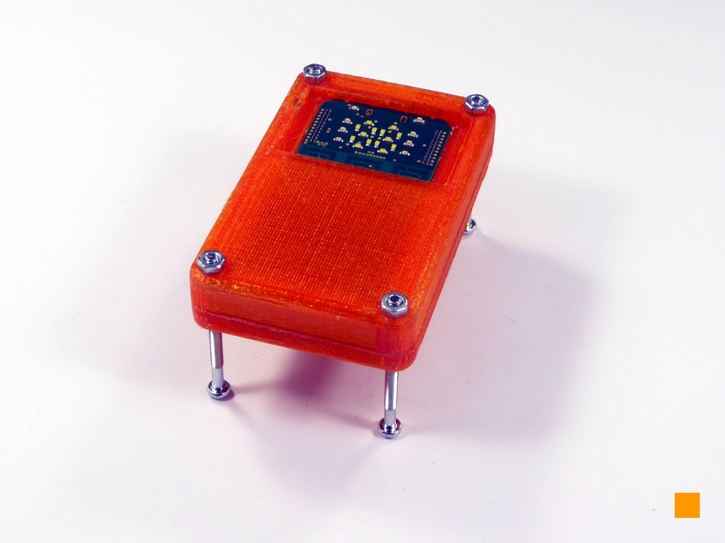
All electrical and functional testing of various components is done in our Cryptoucan™ orange testing box which you can see in Picture 1. With the PCB inside, it allows us to measure voltages, currents, temperatures and it also gives us a serial console for the debug builds of the firmware.

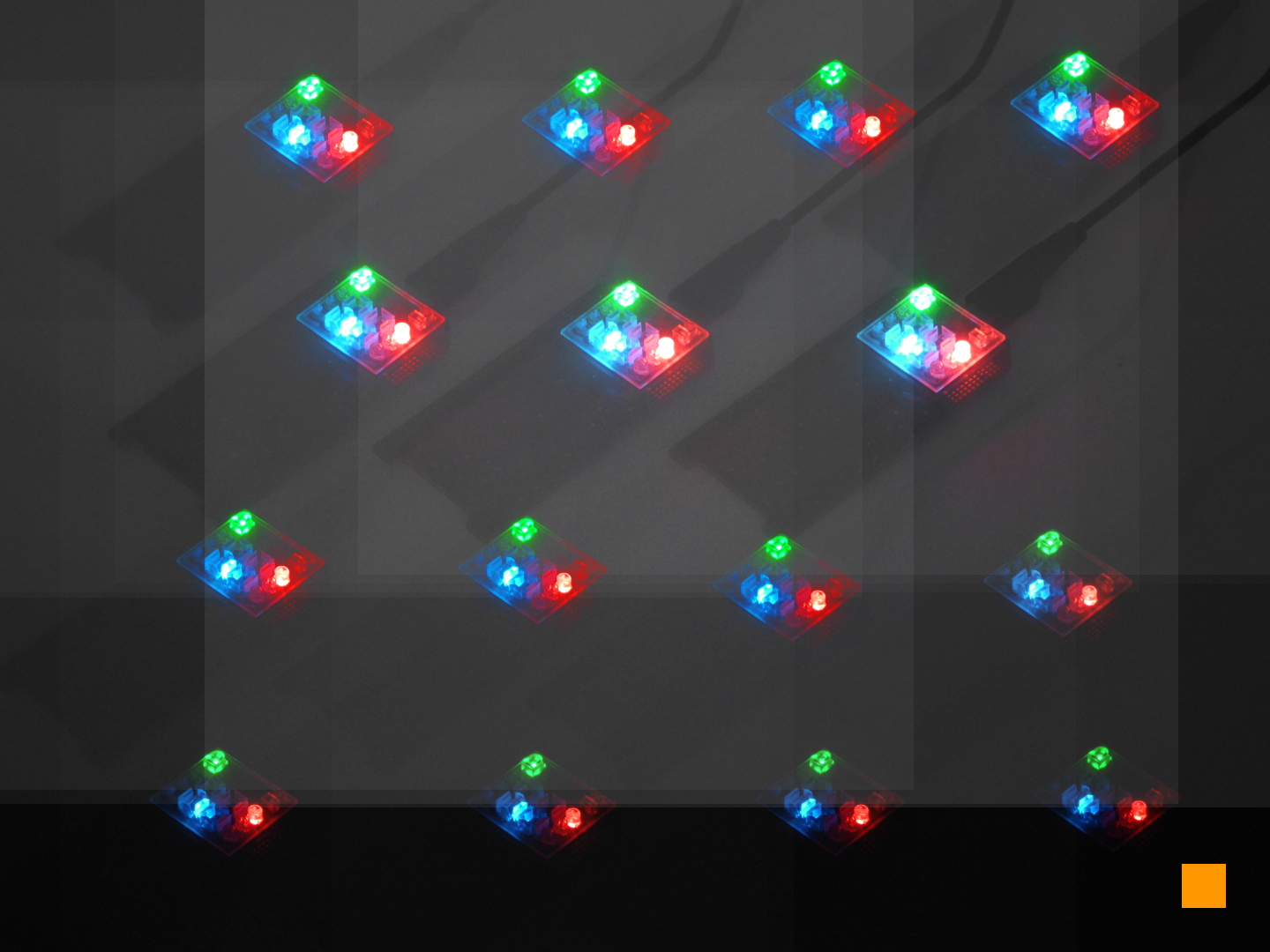
Picture 1: Cryptoucan testing box A completely separate challenge was finding good light emitting diodes[3] - LEDs for short - for Cryptoucan™. As you can see in Picture 2, various colors, tints and luminosities had to be tested. In addition to testing just the LEDs, we needed to calculate the values of resistors used and also setup some circuitry to ensure we can fine-tune the result electrically.

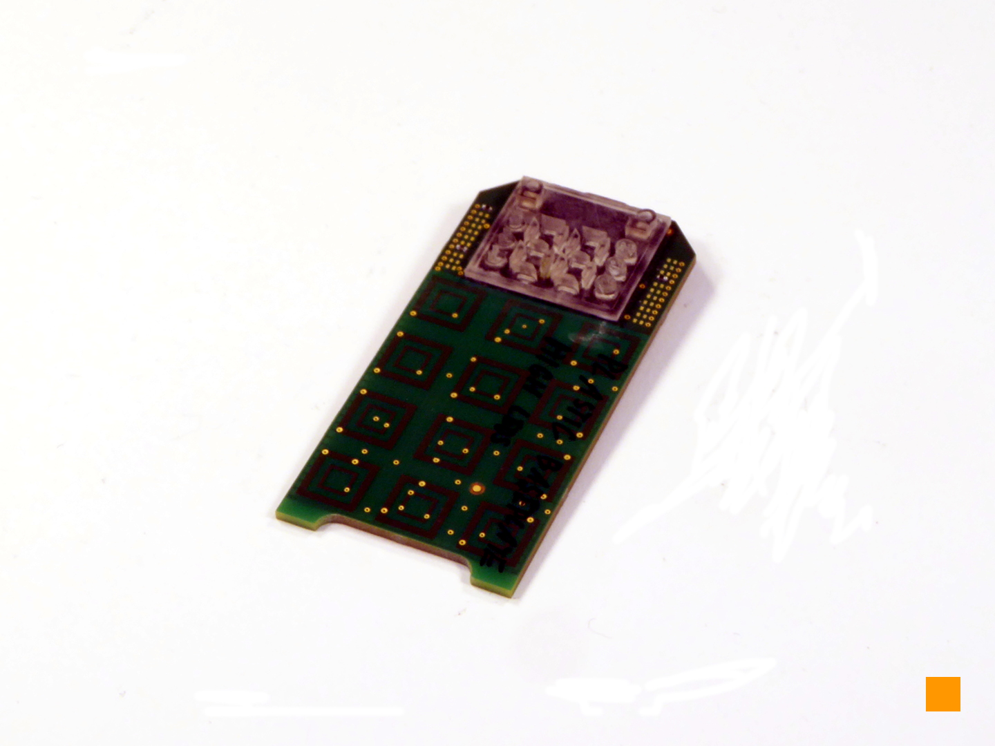
Picture 2: Testing LED hues and luminosities When we knew what colour the LEDs must be and how much they should shine, we needed to ensure they fit into the light guides. As the LEDs just shine into space and the pictograms on the device depict various symbols representing various states of the device, we use transparent light guides to transport the light from the LED to the device surface. As we opted for a single body light guide, we needed to focus the light as much as possible on each symbol. Therefore we needed to find LEDs with reasonably low height. You can see the transparent light guide with underlying black pad in Picture 3.

Picture 3: Transparent light guide with underlying black pad. Producing the light guides in a batch turned out to be yet another challenge. But with the help of our supplier we were able to come out with a 3D printed technique that allows us to produce 40 light guides in a single printing session.
One of our engineering tasks was also the protection against side-channel attacks[4] - for example when some information about private material would leak through measurable differences in power consumption. As you can see in Picture 4, we soldered a few wires, connected Cryptoucan™ to an oscilloscope[5] in our lab and tested it carefully.

Picture 4: Testing Cryptoucan™ with oscilloscope. You might want to have a look at the actual components we work with in motion in Video 1. Although it was sometimes tedious work to perfect each piece, it is safe to say that the result is worth it.
Video 1: About testing various Cryptoucan™ parts.
Thank you for reading this far and next time we will have a look into some practical Cryptoucan™ usage. See you next Thursday!
References
-
https://trustica.cz/en/2018/06/21/cryptoucan-development-a-look-under-the-hood/
-
https://trustica.cz/en/2018/06/28/cryptoucan-development-design-of-the-device-shell/
-
Wikipedia contributors. (2018, June 26). Light-emitting diode. In Wikipedia, The Free Encyclopedia. Retrieved 22:31, July 4, 2018, from https://en.wikipedia.org/w/index.php?title=Light-emitting_diode&oldid=847551245
-
Wikipedia contributors. (2018, June 3). Side-channel attack. In Wikipedia, The Free Encyclopedia. Retrieved 22:32, July 4, 2018, from https://en.wikipedia.org/w/index.php?title=Side-channel_attack&oldid=844202643
-
Wikipedia contributors. (2018, July 3). Oscilloscope. In Wikipedia, The Free Encyclopedia. Retrieved 22:32, July 4, 2018, from https://en.wikipedia.org/w/index.php?title=Oscilloscope&oldid=848624328
